PENN STATE · MECHANICAL ENGINEERING

Julia Langlois

Julia
Langlois

Manufacturing, mechanical design, and analysis.

Seeking full-time engineering roles Summer 2027

B.S. Mechanical Engineering expected May 2027

I’m completing my mechanical engineering degree at Penn State Behrend. My previous work in environmental science involved field equipment, troubleshooting, and improving data-collection workflows.

Explore my work
FEATURED DESIGN PROJECT01 / TEST SYSTEMS

Smart-tire energy
harvesting test rig.

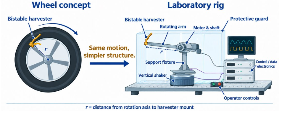
Concept illustration of a tire-mounted energy harvester and a proposed laboratory rig.
Preliminary test-rig concept. Senior design project in progress.

My role
Proposal development, with CAD, component selection, analysis, programming, and testing planned.

Senior design project · 2026–2027
Proposal and requirements phase

Explore the highlighted project
MANUFACTURINGMECHANICAL DESIGNANALYSIS

Projects.

Concept illustration comparing a tire-mounted harvester with a proposed laboratory rig.Concept
In progress

Smart-tire test rig

Senior design project developing a test rig for smart-tire energy harvesting.

View project

Develop a laboratory test rig to evaluate a bistable-beam energy harvester under controlled rotation and vertical vibration.

Research purpose
Support smart-tire energy-harvesting research at Penn State Behrend through development of a laboratory test rig.
Work to date
Contributed to the senior design proposal, including initial project requirements and supporting engineering calculations.
Team deliverables to date
A written proposal, objective tree, engineering specification table with proposed evaluation methods, and project responsibilities and schedule. These are planning deliverables; fabrication and performance testing are future milestones.
Key design challenge
Develop a safe, repeatable test setup by coordinating the mechanical design, instrumentation, and test methods.
Next steps
Compare rig concepts, check motor and shaker capabilities, and develop the mechanical design and analysis needed to select components and plan testing.
Senior designMechanical designAnalysis & testing

MY ROLE

Planned engineering work

  • CAD modeling
  • Material and motor selection
  • Bistable-beam dimensioning
  • Finite element analysis (FEA)
  • Programming
  • Testing and validation

Planned responsibilities will develop as the project progresses.

WORK TO DATE

Senior design proposal development.
Back to projects ↑
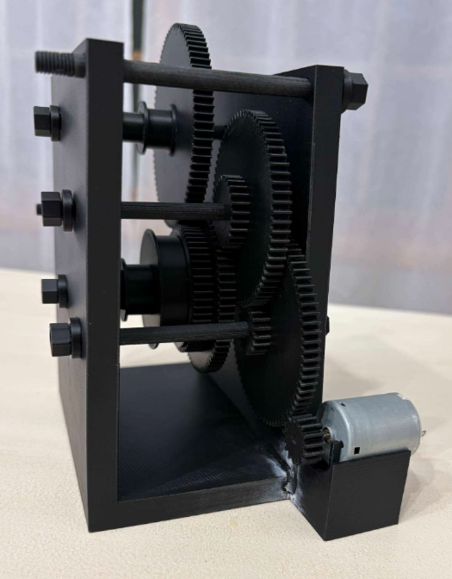
Assembled gear-driven winch prototype with its motor, gears, and frame.
Prototype built

Nittany Lion Lift

Gear ratios and spool radii selected through torque and speed calculations.

View project

DESIGN & ASSEMBLY · FALL 2026

A compact winch with a 3 V motor.

My contribution: Selected the gear ratios and spool radii using torque and speed calculations, and contributed to the team's CAD model. The design includes 60:1 and 90:1 reductions with interchangeable spool sizes.

Prototype: Our team built the winch with 3D-printed gearbox components. The photo shows the assembled gear train, frame, spool, and drive motor.

Next step: Continue load testing and refine the gearing to meet the competition requirements.

Assembled winch prototype with a multistage spur-gear train, two side plates, a spool, and a small DC motor.
Our assembled winch prototype. View full photo ↗
Back to projects ↑
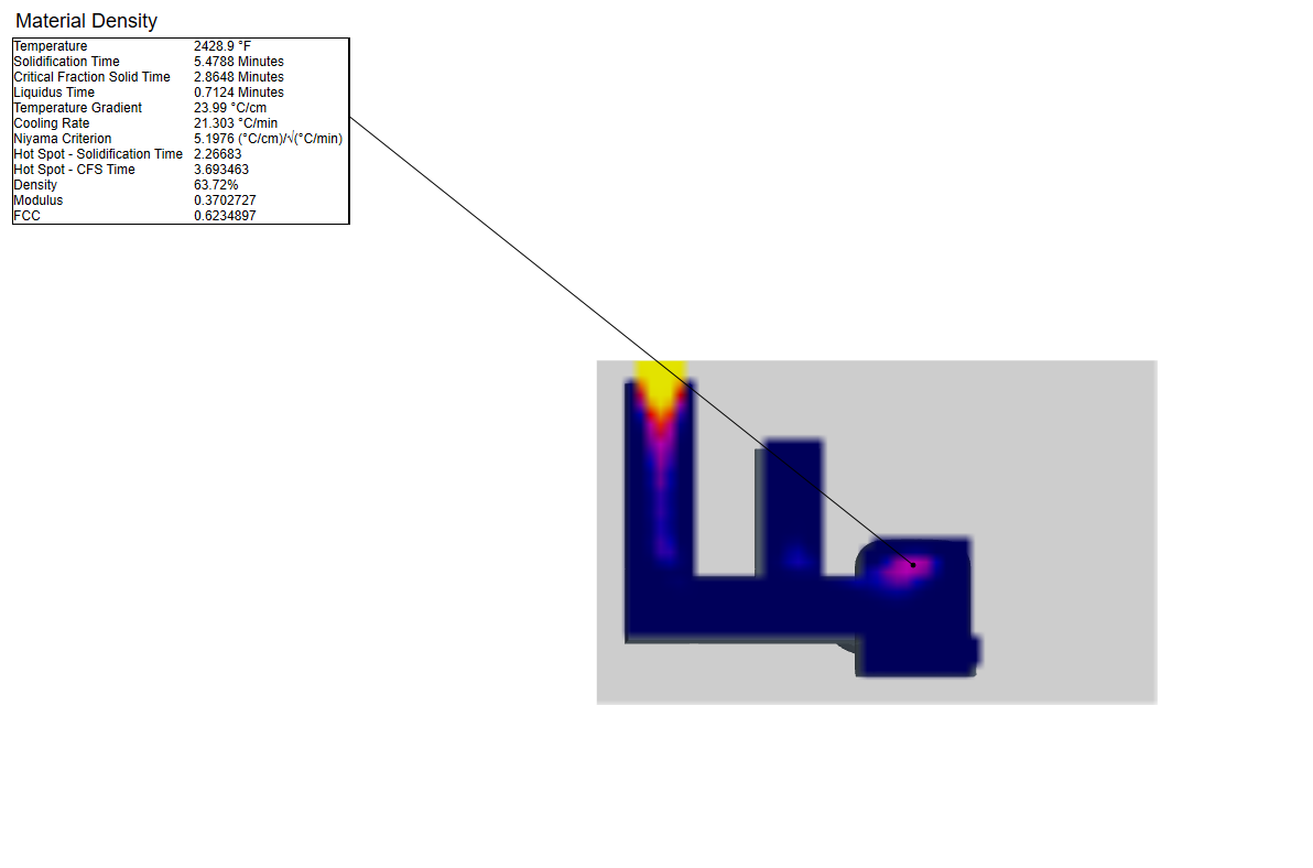
SOLIDCast density result showing the supplied propeller casting geometry with an added riser.Simulation result
Analysis completed

Propeller casting analysis

Comparing riser feeding, solidification time, and hub porosity in SOLIDCast.

View project

Evaluate how adding a riser affects feeding, solidification time, and shrinkage porosity in a propeller casting.

My contribution
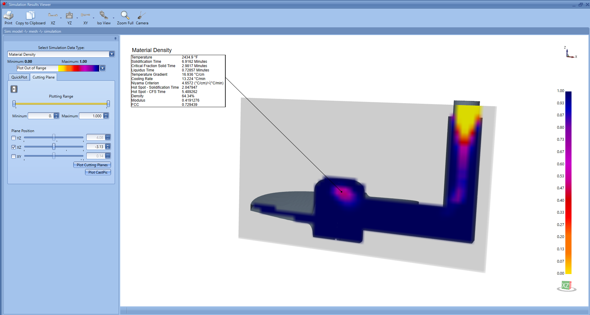
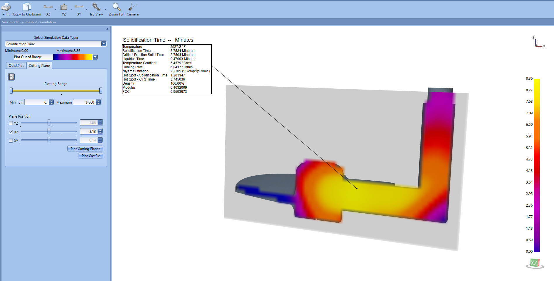
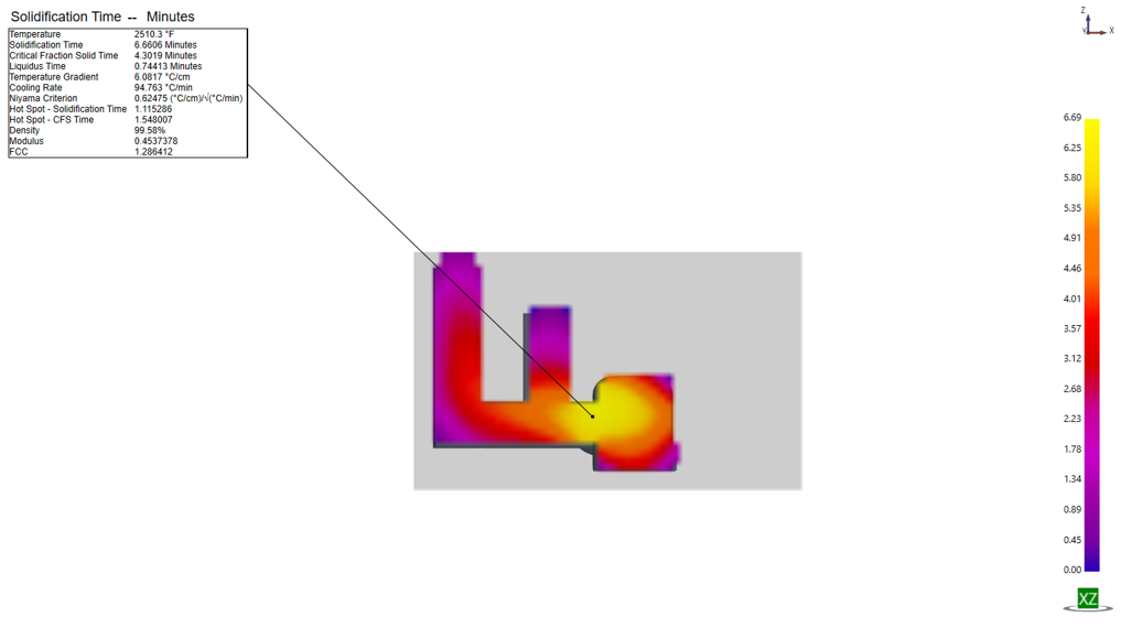
Evaluated two supplied casting geometries in SOLIDCast and examined material-density and solidification-time results to assess riser feeding and hub shrinkage.
Engineering decision
Used density and solidification-time plots together to locate late-solidifying hub regions and assess whether the added riser addressed the shrinkage defect.
Outcome
The maximum simulated solidification time decreased from 8.86 to 6.69 minutes, approximately 24%. The sampled hub density changed from 64.34% to 63.72%; the low-density region remained. The revised design therefore required further development.
Next iteration
Recommended evaluating changes to riser size or position, or adding a local chill near the hub to alter the solidification sequence.
SOLIDCastSolidificationRiser feeding

SIMULATION COMPARISON

The hub defect
remained unresolved.

Results from the two-design study
MeasureBaselineWith riser
Max. solidification time8.86 min6.69 min
Sampled hub density64.34%63.72%
Hub porosityPresentRemained
TIME DIFFERENCE−2.17 min

Maximum time decreased 2.17 min (approximately 24%). Sampled hub density decreased 0.62 percentage points. Low density persisted in the hub, so the riser required further development.

SIMULATION EVIDENCE

Inspect the two designs.

SOLIDCast baseline cutting plane: a low-density region in the propeller hub, with selected-point density 64.34 percent.
Baseline · no added riserSelected hub-region point: 64.34% predicted density. View full image ↗
SOLIDCast revised design with an added riser: a low-density region remains in the hub, with selected-point density 63.72 percent.
Revised · added riserSelected hub-region point: 63.72% predicted density. View full image ↗

These images are from my SOLIDCast report. The density readings are taken at the marked points.

Back to projects ↑
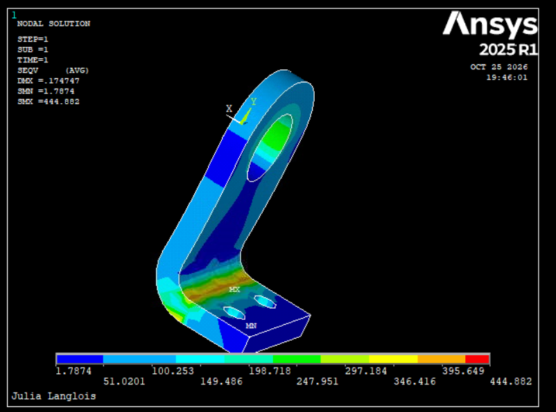
ANSYS equivalent-stress contour of a bracket, with higher stress contours around the bend.Class project
Class project

Bracket structural analysis

ANSYS class project for Intermediate Strength of Materials, examining stress distribution in a bracket.

View study

A class project for Intermediate Strength of Materials using ANSYS to examine stress distribution in a bracket. The image shows the equivalent-stress distribution in a bracket.

Taking Finite Element Analysis in Spring 2027.

ANSYS equivalent-stress contour of a bracket, with higher stress contours around the bend.
Class project result. View full image ↗
Back to projects ↑
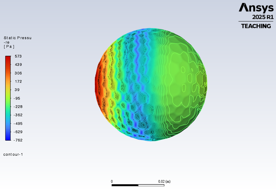
ANSYS Fluent surface static-pressure contour on a golf ball, with pressure values in pascals.Class project
Class project

Flow around a golf ball

Simulated airflow around a golf ball at 30 m/s using ANSYS Fluent.

View study

A CFD class project examining airflow and surface pressure around a golf ball using ANSYS Fluent.

My work
Set up the flow domain and mesh, applied boundary conditions, and ran the flow simulation.
Simulation setup
30 m/s inlet velocity, SST k–omega turbulence model, and SIMPLE pressure–velocity coupling.
Result
Generated surface static-pressure contours to visualize pressure variation over the golf ball. The image below shows pressure in pascals.
ANSYS Fluent surface static-pressure contour on a golf ball, with pressure values in pascals.
Class project result. View full image ↗
Back to projects ↑

Research

PENN STATE BEHREND · FALL 2026–PRESENT

Microfluidic modeling for women’s health

Literature review · Fluent setup planned

Research under Dr. Jun Zhou on using microfluidic devices and CFD to study how vaginal drug-delivery films dissolve under physiologically relevant flow conditions.

Research objective
Develop a computational model of vaginal film dissolution in a microfluidic platform and compare its predictions with experimental data.
Current work
Reviewing literature on microfluidic device design, fluid flow, and drug-film dissolution to inform the model setup.
Planned contribution
Set up ANSYS Fluent flow simulations in the microfluidic device to support the film-dissolution study.
Women’s healthMicrofluidicsANSYS Fluent

Experience

MAY–AUGUST 2026 / NEW YORK, NY

Siemens

Project Management Intern · Building Automation Systems

  • Electrical planning: Calculated equipment VA loads from controls and MEP drawings, selected transformer capacities, and assigned circuits based on electrical limits and cost. Documented the plan in Excel and marked-up drawings, and coordinated installation feasibility with electricians.
  • Alarm review: Audited approximately 1,000 BAS alarm points by comparing drawing requirements with existing alarms in Excel. Worked with project engineers to resolve discrepancies and produced an alarm plan approved by the engineering manager for client delivery.
  • Controls training: Wired relays on a low-voltage training board and completed written controller-logic exercises for temperature-based actuator control.

JULY 2023–PRESENT / NEW YORK, NY

AECOM

Scientist · Full-time through July 2025, part-time thereafter

  • Digital field records: Built a Microsoft Forms and Power Automate workflow that created Excel records from field submissions. The team adopted the workflow, eliminating manual transcription of handwritten notes and reducing data-processing time by an estimated 50%.
  • Equipment troubleshooting: Worked through pump setup and operating problems while purging sampling wells before water collection. Wrote step-by-step instructions for subsequent field staff.
~50%estimated reduction in data-processing time

MAY–AUGUST 2019 / ERIE, PA

Ameridrives International

Mechanical Engineering Intern

Created SolidWorks models of industrial coupling hardware from engineering drawings. Measured couplings and a rotating adapter to develop a safety-bracket concept for engineering review.

Education & tools

julia.langlois@alumni.psu.edu

PENNSYLVANIA STATE UNIVERSITY

B.S. Mechanical Engineering

Expected May 2027 · GPA 3.97
Dean's List every semester

Current coursework: Engineering for Manufacturing, Additive Manufacturing Lab, Machine Design, Applied CFD.
Planned Spring 2027 coursework: Finite Element Analysis.

B.S. Wildlife & Fisheries Science

2023 · GPA 3.96 · Magna cum laude

TOOLS & INVOLVEMENT

SolidWorks · Autodesk Inventor · SOLIDCast · ANSYS Fluent · MATLAB
FDM 3D printing · Cura · Controls and wiring diagrams · P&IDs
Excel · Microsoft Forms · Power Automate · R · Bluebeam Revu

ASME Officer · Tau Beta Pi